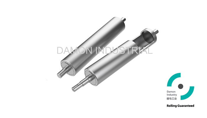
① Driven Pulley:
Main driving component for centre drive belt conveyors:
Select BP-D series pulley (rotating shaft).
② Head & Tail Pulley:
Installed at each end of a belt conveyor according to the different drive type and structure:
a、Centre drive:
Change the belt direction: Select BP-R series pulley (fixed shaft) or DP-D series pulley
(rotating shaft)
b、Head or Tail drive:
Drive Pulley: Select BP-D series pulley (rotating shaft)
Idler Pulley: Select BP-R series pulley (fixed shaft) or BP-D series pulley (rotating shaft).
③ Snub Pulley:
Used to increase the belt wrap angle for the driven pulley, tension and tracking the belt.
Select BP-R series pulley (fixed shaft) or 1200 series conveyor roller.
Be careful about the belt tensionning and siding focce when using as redirection & tensioning.
④ Carrying Roller:
Used to support the belt, simplify structure and reduce friction:
Select 1200 series conveyor roller.
Dimensions(Surface Z/P):

| Standard | Optional | Length |
| Series | Tube dia.(D) | Tube(t) | Shaft dia.(d1) | Drum(D1) | Optional shaft dia.(d1) | W | L | L1/L2 |
| 06C | Φ59 | (4.5) | Φ25 | Φ58 | Φ20 | 250~1300 | ≤1500 | ≤280 |
| 08K | Φ75 | (4.5) | Φ30 | Φ74 | Φ25 | 250~1300 | ≤1500 | ≤280 |
| Φ35 | ≤185 |
| 08J | Φ87 | (4.5) | Φ30 | Φ85.6 | Φ25 | 250~1300 | ≤1500 | ≤280 |
| Φ35 | ≤185 |
| 10B | Φ100 | (6.0) | Φ30
| Φ98 | Φ25 | 250~1400 | ≤1600 | ≤280 |
| Φ35 | ≤185 |
| 11D | Φ112 | (6.0) | Φ35 | Φ110 | Φ30 | 250~1400 | ≤1600 | ≤280 |
| Φ40 | ≤185 |
| 12A | Φ119 | (6.0) | Φ35 | Φ117 | Φ40 | 250~1400 | ≤1600 | ≤185 |
| 13C | Φ130 | (6.5) | Φ35 | Φ127 | Φ40 | 70~1800 | ≤2400 | ≤300 |
| 14K | Φ137 | (6.5) | Φ35 | Φ135 | Φ40 | 70~1800 | ≤2400 | ≤300 |
| 15J | Φ156 | (6.5) | Φ35 | Φ153 | Φ40 | 70~1800 | ≤2400 | ≤300 |
| 18K | Φ176 | (8.0) | Φ40 | Φ173 | Φ45 | 70~1800 | ≤2400 | ≤300 |
| 20C | Φ200 | (6.5) | Φ45 | Φ196 | Φ50/55 | 70~1800 | ≤2400 | ≤300 |
| 21J | Φ216 | (8.5) | Φ50 | Φ212 | Φ55 | 70~1800 | ≤2400 | ≤300 |
Straight tube is available-not tapered ; “( t )”is not accurate data.
If there is dynamic balance requirement for products, please contact us.
Precaution of broken shaft: when installed by shaft through the motor, the torque that the shaft
takes is quite big, please pay attention to the actual torque output and installation detail, otherwise,
the shaft will break. Please contact us for details.
Prcaution of abrasion of the shaft: 1, please install the bearier with frame, and make sure the screw is fastened.
2, Machine flat surfaces on both sides of the shaft, so as that the screws can reach the surfaces and thus be fastened.
Dimensions(Surface Polyurethane-PU):

Standard | Optional | Length |
Series | After PU coating (D) | PU layer thickness (t) | Shaft dia.(d1) | Drum (D1) | Optional shaft dia.(d1) | W | L | L1/L2 |
08J | Φ87 | (6.0) | Φ30 | Φ85.6 | Φ25 | 250~1400 | ≤1600 | ≤280 |
Φ35 | ≤185 |
10B | Φ100 | (6.5) | Φ30 | Φ98 | Φ25 | 250~1400 | ≤1600 | ≤280 |
Φ35 | ≤185 |
11D | Φ112 | (6.0) | Φ35 | Φ110 | Φ30 | 250~1400 | ≤1600 | ≤280 |
Φ40 | ≤185 |
12A | Φ122 | (5.0) | Φ35 | Φ120 | Φ40 | 250~1400 | ≤1600 | ≤185 |
13C | Φ130 | (5.5) | Φ35 | Φ127 | Φ40 | 250~1400 | ≤1600 | ≤185 |
15J | Φ156 | (6.0) | Φ35 | Φ153 | Φ40 | 70~1800 | ≤2400 | ≤300 |
18K | Φ176 | (5.0) | Φ40 | Φ173 | Φ45 | 70~1800 | ≤2400 | ≤300 |
| 20C | Φ202 | (5.0) | Φ45 | Φ199 | Φ50/55 | 70~1800 | ≤2400 | ≤300 |
21J | Φ216 | (7.5) | Φ50 | Φ212 | Φ55 | 70~1800 | ≤2400 | ≤300 |
Straight tube is available-not tapered ; “( t )”is not accurate data.
Polyurethane (PU)color-yellow
(If the pulley length is out of above, please contact us.)
Precaution of broken shaft: when installed by shaft through the motor, the torque that the shaft
takes is quite big, please pay attention to the actual torque output and installation detail, otherwise,
the shaft will break. Please contact us for details.
Prcaution of abrasion of the shaft: 1, please install the bearier with frame, and make sure the screw is fastened.
2, Machine flat surfaces on both sides of the shaft, so as that the screws can reach the surfaces and thus be fastened.


